
KARI PROPRIETARY
Request for Proposal
For
High Frequency Acoustic Source
of LN2 Vaporizer System
August 2015
Korea Aerospace Research Institute
Space Test Division
169-84 Gwahak-ro, Yuseong-gu, Daejeon, 305-806 Korea
Tel: +82-42-860-2562 / Fax: +82-42-860-2234
KARI PROPRIETARY

FRP.KARI.KOREA 2015. 8
2/7
Space Test Division
1. Overview of the project
1.1
Korea Aerospace Research Institute (hereinafter referred to as “KARI”)
is located at Daeduk Research Complex, 140 km south of Seoul.
1.2
KARI has a satellite assembly, integration and test center (hereinafter
referred to as “AITC”) as a research institutes for the purpose of the
effective development of domestic & scientific satellites.
1.3
In the AITC, for the acoustic test, the high intensity acoustic chamber
is operated and can generate the noise of 148dB OVSAL.
1.4
This acoustic chamber uses the low frequency interface and high
frequency interface to generate the acoustic noise, which are parts of
LN2 vaporizer system .
1.5
The purpose of this project is to change high frequency
interface(source) of LN2 vaporizer system in order to maintain the
system performance.
1.6
The supplier should summit the performance record showing the
satisfaction of technical requirements
1.7
The supplier should submit the business showing of sales and
installation records for acoustic source and acoustic chamber facilities.
1.8
All the descriptions in this RFP are minimum requirements and the
supplier can suggest the better one to improve the overall
performance and cost. But in this case, the proposal should clearly
indicate the improvements from KARI’s requirements.

FRP.KARI.KOREA 2015. 8
3/7
Space Test Division
2. Procedure of the project
The project shall be performed as follows:
1) Supply of high frequency acoustic source with amplifier
3. Requisites of participants
3.1
The supply should submit the bisiness showing of sales and
installation records for acoustic source and chamber facilities.
FRP.KARI.KOREA 2015. 8
4/7
Space Test Division
4. Technical Requirements
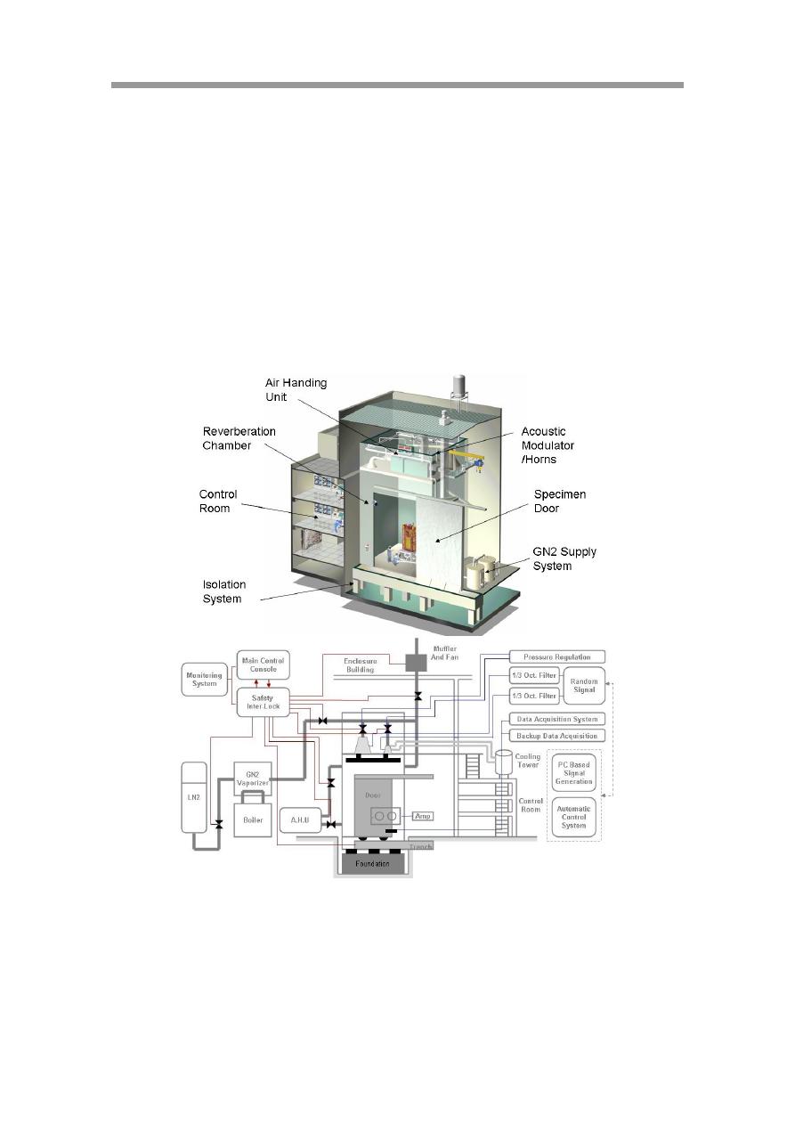
For the acoustic facility, main components are :
- Reverberant chamber,
- LN2 vaporizer system
- Acoustic control system
- Monitoring & Safety system
Figure 1 shows a block diagram of a acoustic facility
Figure 1 Block diagram of a acoustic facility
KARI LN2 vaporizer system is composed of GN2 vaporizer, boiler, source
interface and connection pipes & vlaves.
FRP.KARI.KOREA 2015. 8
5/7
Space Test Division
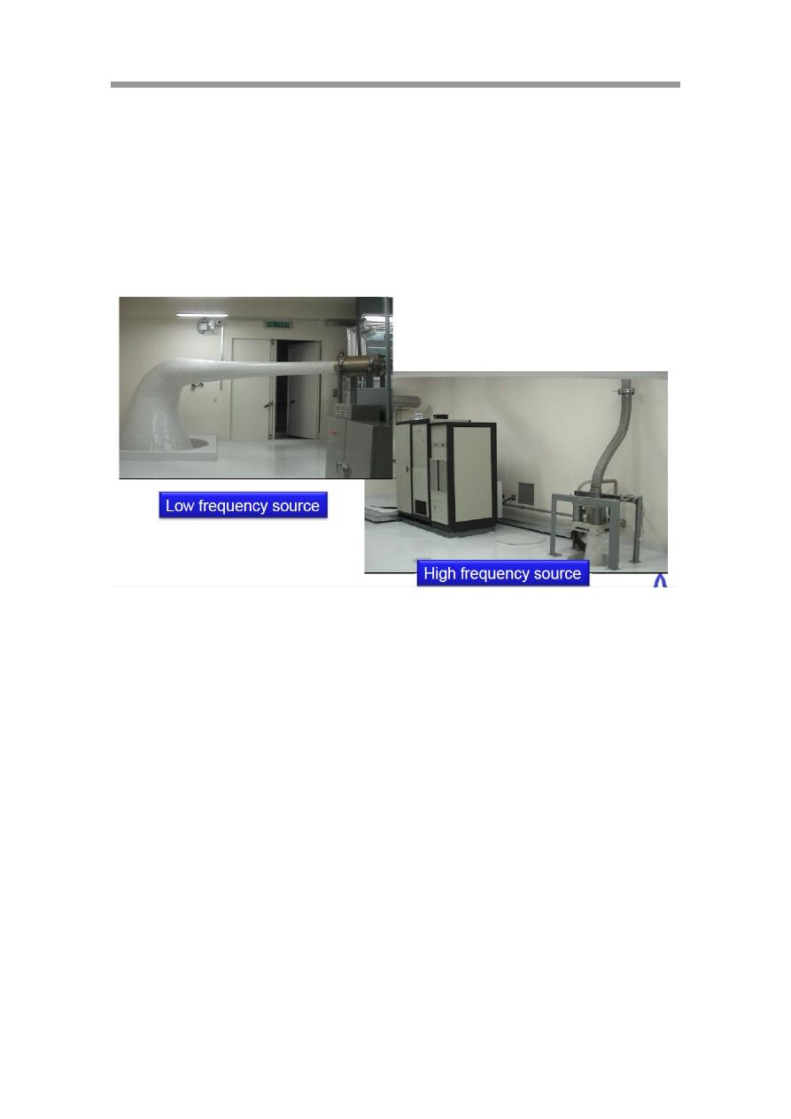
At the end of LN2 vaporizer system, the acoustic source part is connected
with acoustic chamber [Reverberation room]. KARI acoustic chamber
employs the two type of interface which have cutoff frequencies of 25Hz
and 125Hz are employed for acoustic impedance matching. Figure 2 shows
the acoustic source interfaces of KARI.
Figure 2 Acoustic source interface in KARI acoustic chamber
The purpose of this project is to change the high frequency acoustic source
interface in order to maintain performance of LN2 vaporizer system and
acoustic chamber.
4.1 Acoustic electro-pneumatic noise source with amplifier system
4.2 Air flow rate : 1kg/s
4.3 Air pressure required at exhaust plenum housing : 2.5 bar
4.4 Frequency response : 20 to 5000Hz
4.5 Controllability range : 200 to 2500Hz
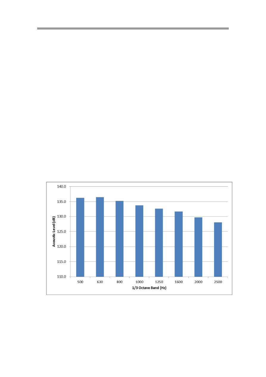
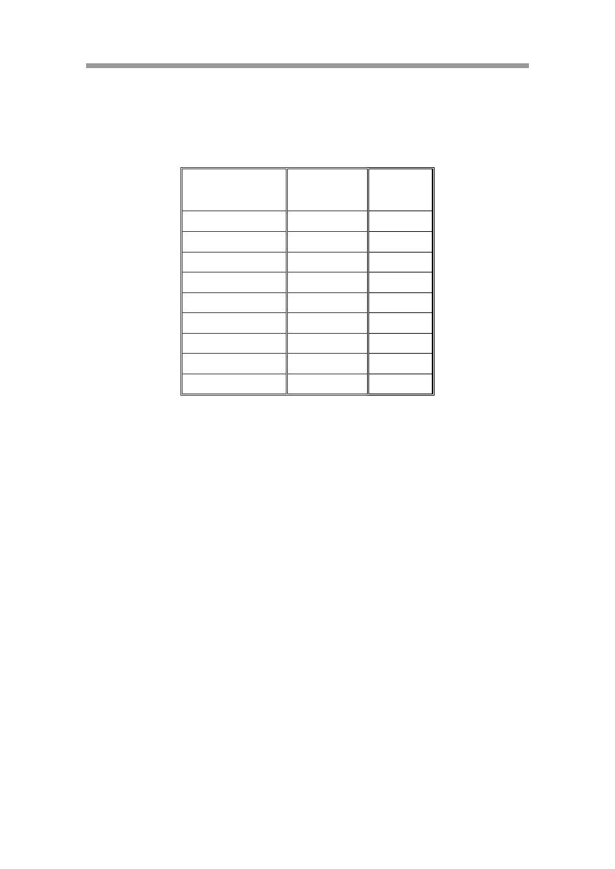
4.6 Generate acoustic spectrum, which is defined at the Table 1 and Figure,
FRP.KARI.KOREA 2015. 8
6/7
Space Test Division
at KARI acoustic chamber (Volume of chamber : 1200m3, Overall T60 :
17.5sec)
4.7 To show the capability of acoustic source interface, the supplier should
submit the measurement results at the acoustic chamber of 1200m3 or more
larger space (Frequency range : 500Hz ~ 2.5kHz).
4.8 The acoustic source should be equipped with sensors to monitoring the
status of source such as displacement of module, pressure, voltage and
current.
Figure 3 Acosutic Spectrum
FRP.KARI.KOREA 2015. 8
7/7
Space Test Division
Table 1 Acoustic spectrum & tolerance at 1200m3 chamber
1/3 Octave
Band (Hz)
Level (dB)
Tolerance
500
136.2
+2/-3dB
630
136.5
+2/-3dB
800
135.2
+2/-3dB
1000
133.7
+2/-3dB
1250
132.6
+2/-3dB
1600
131.7
+2/-3dB
2000
129.7
+2/-3dB
2500
128.0
+2/-3dB
OVSPL
143
+/- 2dB